Filing Manual – Guide E – Change in Class Location (OPR section 42)
- Goal
- E.1 Primary Assessment
- E.2 Determining the Suitability for Continued Service
- E.3 Long-term and Interim Corrective and Mitigative Measures
These revised guidelines detail the CER’s expectation that companies report any change in class location to a higher designation and submit the proposed plan to deal with the change to the CER. Companies are to use the class location change notification module under the OPR section of the Online Event Reporting System for the submission.
A class location change is a change from a previous class location designation (not design class location) to the current higher class location designation as defined by CSA Z662.
Filing must occur within six months after the change occurred. The operator is responsible for monitoring pipeline sections that may be subject to a class location change with sufficient frequency and for engaging and communicating with local authorities or developers in order to be aware of the time of change.
Goal
The submission includes a plan that describes how the company proposes to deal with class location changes to a section(s) of its pipeline to a higher class location designation.
It is the CER’s expectation that the proposed plan demonstrates the adequacy and effectiveness of the company’s integrity management program to ensure the affected section of the pipeline is suitable for continued service at the new class location designation. The CER evaluates the plan for its impact on safety, security, and the protection of the environment.
The plan is submitted within six months after the change of class location occurred.
Identifying Assessment and Filing Requirements
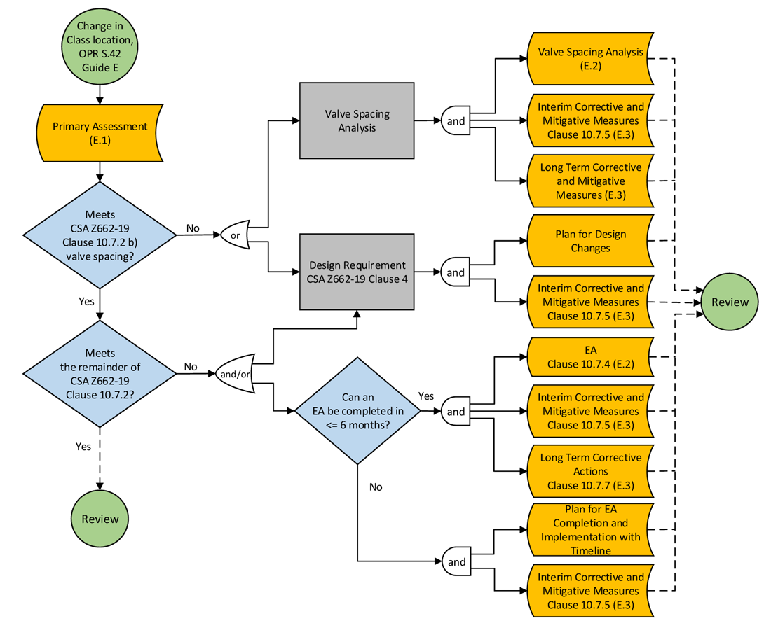
Figure E-1 summarizes the filing requirements to be submitted to the CER for review within six months after a change in class location occurs.
If the class location of a section of a pipeline changes to a higher designation, within six months after the change occurred, submit a primary assessment as part of the proposed plan (as described in E.1) with the CER for reviewFootnote 23.
When the section of the pipeline with the change in class location meets the requirements in CSA Z662 for a new class location, within six months after the change in class location occurred, file only a primary assessment as the proposed plan (as described in E.1) with the CER for review.
When the section of the pipeline with the change in class location does not meet CSA Z662 Clause 10.7.2 requirements for a new class location, the design requirements of CSA Z662, Clause 4 may be applied, or a valve spacing analysis and/or an Engineering Assessment (EA) (as described in E.2) may be performed to determine the suitability for continued service at the new class location designation. In such circumstances, in addition to a primary assessment, file either (1), (2), and/or (3) below, as appropriate, within six months after the change in class location occurred:
- When a company follows the design requirements of CSA Z662, Clause 4, file with the CER for review, the following information:
- The plan for design changesFootnote 24 with a proposed timeline for completion, and
- The interim corrective and mitigative measures (as applicable and as described in E.3).
- When a company carries out a valve spacing analysis to determine the suitability for continued service of the pipeline section at the new class location designation, file with the CER for review, the following information:
- The valve spacing analysis (as described in E.2),
- The interim corrective and mitigative measures implemented to safeguard the public, and
- The long-term corrective and mitigative measures (as applicable and as described in E.3).
- When a company carries out an EA to determine the suitability for continued service of the pipeline section at the new class location designation, file with the CER for review, the following information:
- The EA (as described in E.2)
- The interim corrective and mitigative measures implemented to safeguard the public, and
- The long-term corrective actions (as described in E.3)
- If a company cannot complete an EA within six months after the change occurred, include in the proposed plan the timeline for completion and implementation of the EA and provide the interim corrective and mitigative measures (as described in E.3) implemented to safeguard the public.
Figure E-1: CER Filing Manual Guide E Filing Requirements to be submitted to the CER for review within six months after the change of class location occurred.
E.1 Primary Assessment
Filing Requirements
Subject to the class location change to a higher designation, file with the CER a plan that includes a primary assessment of the pipeline segmentFootnote 25 that includes the following information:
1. Identification of changes in circumstances that have occurred and resulted in the change of class location, including:
- maps of current and previous circumstances in a large enough scale to clearly indicate the following on the map:
- north arrow;
- scale indicated and scale bar;
- reasons for the change in class location;
- location and type of any crossings;
- location and spacing of valves;
- class location assessment area;
- area of potential impactFootnote 26;
- description of development within class location assessment area, including number and type of dwelling units, outside areas or buildings as described in CSA Z662 for class location designations;
- the date or, if not available, the most likely date of the class location change event.
2. Requirements of CSA Z662 for a change of class location, including, as applicable:
- design factor or location factor, as applicable:
- effect of the new location factor(s) on design pressure and hoop stress used in stress analyses for any location on the affected pipeline segment, including road and railway crossings;
- valve spacing;
- depth of cover (DOC) (comparison of minimum requirements versus actual DOC);
- results and source of most recent DOC measurements;
- pressure testing;
- evaluation and repair of imperfections as specified in CSA Z662:
- report the presence of incomplete records or no records of assessed/repaired imperfections on the affected segment of the pipeline;
- clarify if a pipeline segment has been inspected with in-line inspection (ILI) tools. Report the latest dates and types of in-line inspection tools used, if applicable;
- report integrity assessment methods other than in-line inspections (e.g., above-ground surveys, integrity excavations, etc.);
- when pressure testing is performed as an integrity assessment, report the date of the final pressure test and the hoop stress at the test pressure as a percentage of the specified minimum yield strength.
3. Design and operating conditions of the pipeline system, including service fluid, design operating stress, maximum operating pressure (MOP), joint and temperature factors, and the presence of potential geohazards:
- report if the pipeline segment is under a regulatory or self-imposed operating pressure restriction.
4. Material and pipeline properties, including in-service year, seam weld type, outside diameter, wall thickness, specified grade, yield strength, tensile strength, and toughness, and how the material properties were obtained.
5. Coating type and condition of the coating applied to the pipeline body, girth welds, and repairs:
- report the source of the coating information, which may be inferred from specifications, construction records, and indirect inspection (e.g., ILI, electromagnetic acoustic transducer (EMAT) inspection, above-ground inspections (e.g., direct current voltage gradient (DCVG), alternating current voltage gradient (ACVG), alternating current coating attenuation (ACCA), etc.)), and excavation results.
6. Level of cathodic protection (CP):
- report the date of the last potential survey (e.g., test lead survey, closed interval survey (CIS), etc.).
7. Confirmation that girth welds of the affected segment of the pipeline were subjected to 100% Non-Destructive Examination (NDE).
8. The damage prevention activities at the location of the pipeline segment subject to the increase in class location (e.g., additional signage, slabs, patrol frequency, etc.).
9. The presence of a school, hospital, day home, assisted living facility, prison, or other facilities that may be difficult to rapidly evacuate and/or where evacuation from such facility can only be achieved by entering the areas of potential impact.
10. Failure history of the valve section containing the affected segment of the pipeline.
E.2 Determining the Suitability for Continued Service
Filing Requirements for a Valve Spacing Analysis
When the valve spacing requirement of CSA Z662-19 is not met for the higher class location designation, a valve spacing analysis following CSA Z662-19 Clause 4.4 is required to demonstrate the suitability of the valve spacing for the new class location. File this analysis and include the following information, as applicable:
1. A listing of the upstream and downstream sectionalizing valves, including a map that shows the spacing of the valves;
2. A listing and a schematic of the current configuration of the branches, cross-overs, risers and other piping that feed service fluid between the two sectionalizing valves, including:
- confirmation that the additional feed from each source is accounted for in the calculation of the blowdown volumes;
- details on the cross-over valve assembly;
- normal operating settings for each of the valves (e.g., normally closed or open);
3. Information on both 1 and 2, including:
- valve mechanism (remote, automatic or manual);
- clarification whether valves are equipped with emergency shutdown mechanisms;
- valve maintenance frequency;
4. A risk analysis that demonstrates that the risks of the pipeline at the existing valve spacing are equal to or lower than the risks of the pipeline at a valve spacing that meets the requirement of CSA Z662-19 Clause 4.4 for the changed class location.
Filing Requirements for an Engineering Assessment
When the requirements of CSA Z662-19, Clause 10.7.2 other than the valve spacing are not met for the higher class location designation, an EA is required that includes, as applicable:
1. Primary assessment (as described in E.1);
2. The EA must meet CSA Z662 requirements for engineering assessments of existing pipelines, including, as applicable:
- manufacturing process and installation method;
- construction and testing specifications;
- the physical configuration and constraints of the affected section of the pipeline that is the subject of the engineering assessment;
- condition of the piping, including types of imperfections, dimensions, and dimensional uncertainty;
- mechanism or mode of imperfection formation, growth, and failure;
- service, operating, failure, and maintenance history, including a CP effectiveness evaluation;
- appropriateness of repair methods used;
- consideration of combined stresses, for example:
- where existing pipelines are crossed by roads or railways, upgrade the pipelines to meet the applicable design requirements for the new class location or perform a detailed analysis of all loads expected to be imposed on the pipeline during operation of the crossing. Consider the condition of the pipeline when determining the resulting combined stresses in the pipeline. Consider fatigue stress or fluctuating stress if heavy equipment crosses the pipeline at high frequencies.
3. A comprehensive hazard identification and assessment is required with regard to the condition of the piping, performed by a professional engineer who is competent in assessing the hazard, considering as applicable:
- corrosion (e.g., external, internal, microbiologically influenced corrosion (MIC), alternating current induced corrosion, etc.):
- apply additional coating inspection and testing if the information of the coating condition of the pipe body and girth weld is lacking;
- perform additional coating assessment or apply additional safety measures depending on how effectively the coating protects the pipe or depending on the probability that it may support the presence of a corrosive environment on the pipe;
- cracking (e.g., environmentally-assisted, fatigue, etc.);
- mechanical damage (e.g., dents, wrinkles, buckles, and gouges):
- visually inspect all dents on the top half of the pipe (8 o’clock to 4 o’clock) and all dents with a length to depth ratio less than 20 for cracks, gouges, corrosion, and interaction with welds unless the company can demonstrate the absence of stress concentrators and interactions with welds;
- geohazards (e.g., soil movement, seismically-triggered hazards, scour, erosion);
- manufacturing and construction-related imperfections (e.g., imperfections in welds, in the pipe, or imperfections of pipeline components);
- equipment malfunction (e.g., malfunction of control or relief equipment as a result of ice formation in cold weather);
- incorrect operation (e.g., overpressure, incorrect operating procedures, introduction of out of specifications fluids);
- potential stresses as a result of thermal expansion or contraction;
- material-related issues (e.g., low toughness);
- interaction of identified hazards.
Include the tool performance specification and tool performance validation in a hazard assessment using in-line inspection (ILI) results. Include all excavation results on the pigged pipeline section and all false negatives in unity plots.
Performance history alone is not an adequate hazard evaluation technique; the absence of a previous leak or rupture caused by a hazard on the pipeline is not proof of the absence or control of a hazard.
Evaluate and repair all imperfections identified in the assessment of the condition as needed. The repair must meet the requirements of CSA Z662 Clause 10 and be scheduled appropriately, independent of the EA timeline.
4. Consider the potential for collateral damage to pipelines or other buried facilities caused by the failure of adjacent pipelines (e.g., thermal radiation causing coating damage or reducing the strength of adjacent pipe).
5. Submit a risk assessment that identifies and quantitatively demonstrates that the risks of the existing pipeline are equal to or lower than the risks of a pipeline that is at least at the DOC of the existing pipeline and meets all the requirements of the OPR and CSA Z662 (e.g., such a pipeline may have a heavier wall, be constructed of a higher grade, or may be operating at a lower pressure).Footnote 27 Examples of quantitative risks for gas pipelines are individual and societal risks. Include the following information in the risk assessment:
- a reliability or probability of failure (POF) assessment that includes:
- all identified hazards and potential interactions;
- the source of failure probabilities (i.e., references) used in the assessment, where the methodology is representative and specified;
- long-term plan on maintaining the reliability of the POF level;
- a consequence analysis and results:
- for HVP and sour service pipelines, consider the potential effects of fire and the potential effects of drifting hazardous gas mixtures beyond the area of potential impact prior to ignition;
- identification of long-term mitigative measures that the company identifies as necessary to achieve an acceptable risk level:
- document the evidence supporting the effectiveness of the mitigation methods and measures considered and proposed, and provide this with the EA.
E.3 Long-term and Interim Corrective and Mitigative Measures
Filing Requirements
1. Provide a description of long-term corrective and mitigative measures and an implementation plan with timeline for completion, where applicable, to address the identified potential concerns. Implement long-term corrective and mitigative measures as soon as practicable.Footnote 28
2. Provide a description of interim corrective and mitigative measures taken until the requirements of CSA Z662 are met, or long-term mitigative measures are implemented. Implement interim corrective and mitigative measures as soon as practicable. Include:
- explanations as to why each interim measure was determined to be appropriate to ensure continued safe operation until the completion of the long-term corrective and mitigative measures;
- confirmation that each recommended interim measure was implemented, and will stay in place until the completion of the identified long-term corrective and mitigative measures:
- if a recommended interim measure has not been implemented, provide a plan for implementation;
- demonstration that the pipeline segments can be operated safely without any additional interim measures until the completion of the identified long-term corrective and mitigative measures, if no interim measures are recommended.
Corrective and mitigative measures may include:
- modifications to the pipeline system, which may include consideration of pipeline replacement;
- reduction of the operating pressure to that specified for the changed class location:
- reduce the operating pressure as a corrective or mitigative measure as soon as practicable following its decision, with an explanation as to what was considered in assessing the timing of the practicability of implementation;
- the approved MOP will be adjusted to the new reduced operating pressure, following CER approval of a long-term corrective measure of a reduction in operating pressure as per the proposed plan pursuant to OPR section 42;
- increased public communications on the location of the pipeline;
- installation of structures or materials (e.g., concrete slabs, steel plates) for mechanical damage protection or for protection against other external loads;
- increased integrity assessments (e.g., in-line inspections), and repairs;
- restricted access to the pipeline right of way; and
- increased signage and right of way patrols frequency.
- Date modified: